1/6th Dragon Sherman – Idler Upgrade
Price range: $30.00 through $50.00
RC conversion parts for the 1/6th scale Dragon Sherman Check out the assembly video below:
***Image will be added soon
Description
FEATURES
- Adjustable from inside the tank with just 1 screw!
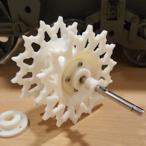
- Idler wheel fully supported with bearings
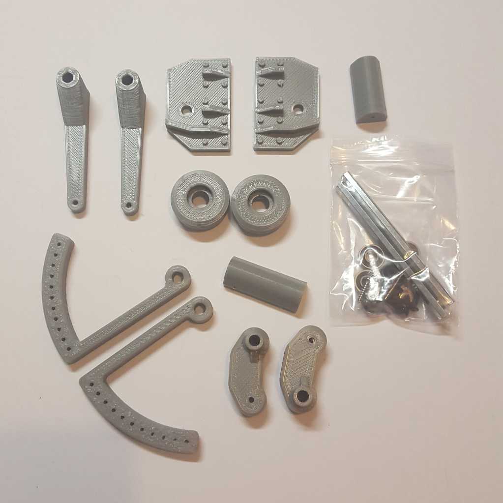
INCLUDES
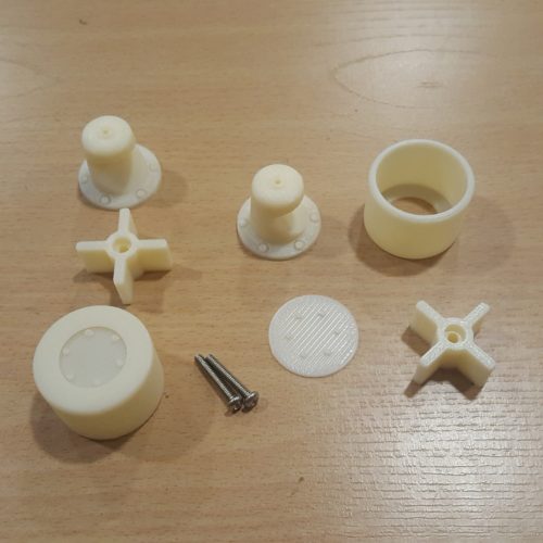
- Printed parts
- Hardware
REQUIRES
- Assembly
Additional information
| Weight | 1 lbs |
|---|---|
| Dimensions | 8 × 8 × 3 in |
| Type | Full KIT, Hardware Only |
2 reviews for 1/6th Dragon Sherman – Idler Upgrade
Only logged in customers who have purchased this product may leave a review.
Related Products
-
1/6th M5 Stuart – Sprockets
$80.00 Add to cart -
1/6th M5 Stuart – Return Wheels
$50.00 Add to cart -
1/6th M5 Stuart – Delrin Tracks
Price range: $425.00 through $475.00 Select options This product has multiple variants. The options may be chosen on the product page
sassgrunt (verified owner) –
Ryan’s idler upgrade is the first thing I’m adding to my Sherman. I have to say that the parts are very precise, and his attention to making all the parts fit each other is amazing. I especially like the videos that he makes – they are a great help in assembling everything!
I varied from the video instructions in a couple of places. First, I glued the side plates onto the hull and let them dry overnight before drilling through the hull. The video suggests drilling a 1/4″ hole through both, and then drilling the hull out to 5/16″. The hexagonal shaft that goes through these hole is 1/4″ across the flats, but is 9/32″ across the corners. Therefore, I glued the side plates on first, and then drilled through both them and the hull with a 9/32″ drill. I also used the 9/32″ drill on the “arc” pieces that are glued on the inside, and also on the long sleeves that are put on last. That made it much easier to assemble everything.
I had a heck of a time trying to file out the hex on the end of the long arms so that it would slip onto the hexagonal shaft – no matter how much I tried, it was still too tight a fit to allow me to get the arms onto it. What I did was to take a 1/4″ hex key and drive it through the hole on the arm; which gave just enough clearance to push the arm on by hand.
Lastly, I was looking at ways to mount the outer idler hub onto the inner part; so that I could still remove it in the future if needed. What I did was to glue a 0.015″ by 0.188″ strip of styrene around the edge of the inner hub piece, so that it takes up the slack in the outer hub (Dragon molded it with a taper, so there is a small gap around the edge where the two meet). It’s now a tight press-fit onto the inner hub, but can still be pulled off. It is tight enough that I do not think it will shift when running.
I’m very happy with the upgrade, and am looking forward to working on his other Sherman products.
ThomasJW (verified owner) –
This is an interesting upgrade. The kit goes together very easily with minor mod to stock parts. Clearly some tweaks were done by Ryan since his instruction video, and even since the previous reviewer, in two areas:
1. The tolerances were relaxed in the printed parts that slide onto the hex shaft. Maybe a little too much in one instance. I did not experience any difficulty with any parts sliding onto the hex shaft. You still have to press fit the aluminum standoff and the hole in the idler flange that gets glued to the outside of the hull remains a tight fit but the holes for the hex shaft in the swing arm, the inside adjustment arm, and the last long bit of printed part on the end of the shaft were all slightly over-sized. I think the hole in the adjustment arm particularly is now a weak point in the kit since it loosens what should be a very tight connection. There is too much flex allowed once everything is screwed down in all but the most extreme ends of the track tension adjustment. This brings me on to the second tweak I noticed …
2. You can now adjust the track tension over the full length of the ‘arc of holes’ in the anchor piece. In the video, you can see that Ryan was only able to adjust the arm by placing it at either end of the ‘arc’ and then having only a few holes for adjustment. He mentions of possibly tweaking the rotation in the print file and he must have done this because it is now possible to position the arm is such a way as to be able to use any hole to anchor the adjustment arm. When the arm is fully forward on the last hole, the idler wheel is extended fully backward and is almost spot-on with the scale position. Pulling back on the adjustment arm to the ‘top’ hole swings the idler down and forward to lessen track tension. As mentioned above though, if you position the adjustment arm to any position between the opposite ends, there is a slight forward/backward play in the idler. To eliminate the play, it’s necessary to fully tighten the hex shaft end screw to ‘squish’ everything together. This will have to wait until the treads are installed and adjusted. Then everything will get screwed and glued.
A last item to note is Ryan replaced two pan head screws with flat headed ones. He said he was going to do this in the video but gave no explanation why. The intent must be to screw it in even with the surface of the swing arm so it doesn’t interfere with the stock part that needs to be cut. You’ll need to countersink a small bevel around the hole. Take care if you use a drill for this as it can easily ‘bite’ into the plastic and … well you’ll find out.
Up next … liassez les bons temps rouler !
Cheers.